Building Your Own CNC Router

Now the first things we need to consider when building a router is the length of each axis like say we want a X axis of 800 mm, a Y axis of 300mm and a Z axis of 150 mm

Exif_JPEG_420

here is a pic of my X axis showing how the nut is held and also the linear bearings where the shafts need a good clean with some 1200 emery cloth

For the Y and Z axis heres a pic to show

Exif_JPEG_420

As you can see the Y axis is a metal block with oil light bearings and by making this with no slop the Y axis ball screw works just fine.

Also one can see the Z axis where 2 each linear bearings are used and the ball screw is a 2 start thread so rapid up and down motions can jad for drilling at high speed and also for quick withdrawal. Also one will notice the runner for the stops on each axis.

I can go into more detail later but here is the grasp.

Cheers Bryan

1.5Kw Motor Conversion

Hi guy’s,

Back in 2009 I decided to make a start making my own motor conversions for a wind generator.

This post will detail the build where the magnet arrangement is in the Offset pattern. The Offset pattern is where the 8 magnets, 4 south facing and 4 north facing are spaced at less than 45 degree angle to eliminate the cogging. Now if the magnets were placed at 45 degrees  they would all be aligned and it would need a huge set of stilsons just to move the shaft.

So after talking with online colleagues I settled on a 43.75 degree spacing which after drawing the setup in autocad it turned out to just about right.

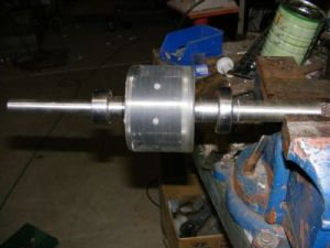
Now rather than machine the existing rotor I decided to machine a new one out of a steel shaft to the dimensions I designed in autocad.

rough machined rotor

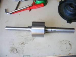
I machined the smaller diameter on the left which holds the dual ball bearing longer than needed to allow for a fan to put at the rear of the motor. The output shaft was machined to 25mm for the conlock fitting for the blade mount.

taperlock

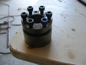
This conlock fitting is designed to clamp shaft and bore where both are parallel. Thus not needing a keyway and the lock is easily broken using the cap screws.

taperlock_centre

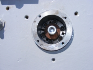
For extra safety a 10mm tapped hole and cap screw is used just for piece of mind.

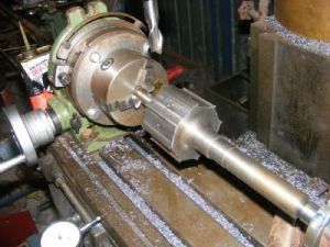
Now in order to machine the flats on the rotor I setup my Bridgeport milling machine with my rotary table and used a 5/8″ slot drill to machine the flats. For the 43.75 degree spacing used 43.75, 87.5, 131.25, 175, 218.75, 262.5, 306, 349.75 which was easily dialed in as the rotary table does have have a vernier scale.

machining rotor

The magnets I used were 2x1x1/2″ N42 epoxy coated with a 3mm countersunk hole which I bought from America. Each magnet lightly screwed in then I poured some Stupid glue (superglue for the many) under each magnet then tightened it down. The next job a casting the rotor in epoxy to totally seal the magnets and also allow me to fully machine the casting to ensure the rotor shaft was balanced.

finished rotor

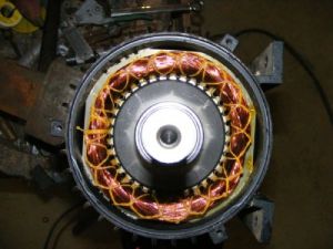
I machined the OD for a total of 2mm clearance on the ID of the motor housing, put the bearings on then using a chain block on my 2 tonne engine hoist (with several large steel billets positioned to counter act any pull from the magnets) and lowered the rotor home.

ebd veiw of motor

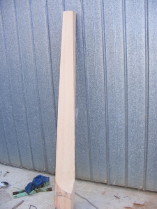
Now for the blades I decided to make a 3 metre set for my first real attempt at wind turbine blade. At the local scrapyard I came across some old Oergon posts then after making some templates for the angles got stuck into carving out the excess.

Here is a pic of the first blade under way.

carving blade

Here is a picture of the project finally finished and up and flying.

finished conversion

2hp up and flying

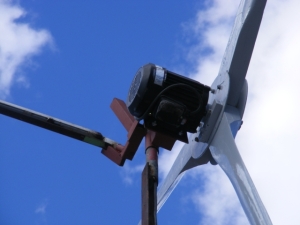
This my first motor conversion is still up and working today and recently it was brought down for a bearing replacement. It has seen many 100+ K winds and loves them and when it’s doing 500+rpm in high wind a small noise can be heard from the blades over the noise of the wind, where at lower speeds they are silent.

Wind Generators

Ok here is my idea to provide the world with my concept of making a wind generator to stand the test of time and be (when the wind blows) a reliable source of power.

My idea comes off years of research where an online user called Zubbly showed how a 3 phase motor can be turned into a wind generator. By replacing the rotor with a new rotor containing magnets in one of two configurations one can have a reliable wind generator that won’t burn up as when the wind blows to an extent of high speed the generator will plateau and actually go down due to motor reactance.

So my concept will provide a reliable wind generator at an acceptable cost .

Now down to the nitty gritty………

As 3 phase motors are used as the base for this design I do think for now sourcing them from China  will be the best cost base as there are no real motor builders left in Australia. (Come in Mr.Song)

Now for the magnets, I will design in Autocad the profile needed for the rotors and get (Mr.Song) to quote a price.

As far as the machining of the new rotor I have an off grid machineshop to make them and as summer is coming along on my off grid system it is machineshop fun time.

Where the motors need to wound with new wire the one wire test with the new magnet rotor must be done to determine the amount of turns to be wound so for the voltage needed the turns on the windings can be worked out.

Ok with using used 3 phase motors Zubbly said go off the plate rating of current and that will get you an average of what the wind generator can do. So lets say and I have done this that 2hp I did as my first conversion has lasts 7 years and I brought it down for a bearing replacement, the 3 metre blades I made out of Oregon boards I got cheaply are standing the test of time.

Now we need to think about what the power of these Wind Generators can do and think about controls to dump power if the batteries are charged.

This is where I want to bring young kids and teach them and provide a safe working place where elderly folk are welcomed to provide support ( and an income).

What is needed is an investor to provide the needed funds to get this concept off the ground so I can teach the young kids of today how the wind can be your friend. Where this free trade agreement with china is expected to wipe out manufacturing in this country it should be abolished and the natural interest be counted as the main priority.

Regards Bryan

P.S. To continue

Uppsndowns from the Start

G’day Guy’s,

Uppsndowns is a 85 acre farm situated in the Adelaide Hills in South Australia. We bought the farm in 2003 fulfilling the agreement if we moved back to SA we would find a small farm and get out of the metro so our kids can have the best life away from the riffraff of today’s society. We knew the place was off the grid and with the paltry system in place I thought well lets take advantage of the govt rebate and put a new off grid system in place.

As I was working on a major mine site construction project doing 3 on 1 off (weeks that is) we went and looked at what was available. We ended up going with the SolarShop and getting a 25K package which after the rebate cost us 18K. Well thats when the fun started I got home from work to find when they put the remote where we asked they just put some white conduit external to the building. When they came out for the quote I told them the wiring WAS to be in the wall and I did show them the point of placement and explained how easy it would be. They did come back and do the job properly and while they were there I asked them about the whole setup and the problem I had found. The batteries 2 volt 600AH Sonnensheins have a max charging voltage of 29 volts and I found the voltage going over 30 volts when charging.

This got me thinking and with my spare time I started researching off the grid living and with only a 56K modem it was slow with big downloads.

Well the boss came out with his tech to look at our system and the boss in my opinion a total asshole (after phone conversations). He opened up the 80 amp charger and turned a trim pot a few turns and said that will fix it when the tech turned around and said lucky I counted the turns and get out of the way and I’ll fix it properly. The boss turned around and said I am playing golf and we are leaving in 5 minutes to where I told him he aint leaving until I’m happy it’s fixed.The tech guy said we can’t leave until the batteries are fully charged so I can set the parameters and by the way it’s charging it will be under the hour. Thats when the boss put his foot down and said just set the F’ing thing as we are going.

Well everything seemed fine for 3 years until the maxuim power point tracker started showing problems like I saw some magic smoke and it wasn’t charging the batteries. I got to talk with guy who knew the MPPT’s and said to me get it off line now as these things will catch fire. Well with that news and me getting back home from work, first off I rang the insurance guy (Elders) he said to go find one and we will cover it. So I went back to the solar shop and asked. Well got fobbed around then the tech guy that came out that day walked thru a door and said we don’t do off grid instals anymore and the boss said not to deal with you so we can’t help you. I went over to to a place in Propect whre I got to talk with the guys and get at a Outback FM 60 MPPT, I rang the insurance guy and said well mate the exact replacement is over 2K and is prone to catch fire and the guy who designed it is dead but I found a newer one that is half the price. He told me to grab it and email the details for payment. The main problem was my system was still offline so we had to run a genset and charge the batteries that way. The insurance paid for everything which was petrol for running the genset, loss of food and the main thing the new Outback.

Well the above is a personal account on dealing with the owner of the solar shop which he sold for millions and left 100’s of people worse off. I’ll leave that one there.